


the progess.
week 5 (june 4 - 8).


week 6 (june 11 - 15).
week 12 (july 23 - 27).


week 13 (august 27 - 30).


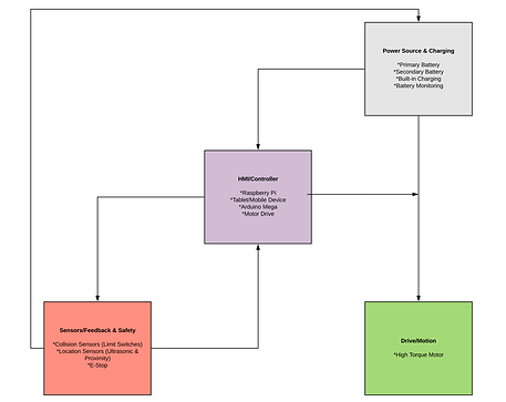
For the second video, I have 3 bump sensors (limit switches), which are attached to two wooden bars with springs in between so it can act like a button. When the bar is pushed, it will press the three switches causing the buzzer to go off.
I have eight ultrasonic sensors working simultaneously, where each has a effectual angle of <15, and a set range distance of 30cm for testing purposes.
A buzzer is attached to notify the user when something is in the range of the sensors.
week 14 (september 3-7).

Raspberry Pi 3 B+ came in. Q had problems getting the raspberry pi to connect, only showing a red LED. memory card was formatted and now the pi is ready for action.
week 15 (september 10 - 14).

Here are two Nema 17 Bipolar 1.7A Stepper Motors programmed to run simultaneously in opposite directions, driven by a TB6600 4A 9-42V Stepper Motor Driver, powered by a 12V, 5A power supply.
week 16 (september 17 - 21).
This week was a rough week for the Raspberry Pi. We are currently on our second Pi, the first one will not turn on after using the GPIO incorrectly. Above is a demonstration of the Pi turning the LED on and off using the ports built on the Pi.


After the first SunJoe unit was defective, the second one arrived half-way through the week fully functional and modifications began. With the correct weight from the defective unit, we were able to finalize motor and gearbox calculations along with place the orders.

In order to make the location system work, we need a very accurate system to tell us where we've traveled. The best way to do this is to reference a completely passive system. The caster above works as an encoder in that it will tell us how far we've traveled as accurately as 1.5" and it has a digital compass which tells us the direction in which we've traveled. These two feedback components provide us with an extremely reliable location monitoring system.
week 17 (september 24 - 28).


Here are two Nema 23 Bipolar 1.7A Stepper Motors, which we will use as the back wheels of the autonomous lawn mower. It's programmed to run simultaneously in opposite directions, driven by a STEPPERONLINE CNC Stepper Motor Driver 1.0-4.2A 20-50VDC 1/128 Micro-step Resolutions, powered by a 24V, 5A power supply. The Nema 23 stepper motor has a length of 100mm and 3.0Mm (425oz.in) torque, and is known as a hybrid stepping motor that can be used as a unipolar or bipolar stepper motor and has a 1.8 step angle (200 steps/revolution). Bipolar drivers use H-bridge circuitry to actually reverse the current flow through the phase. By energizing the phases with alternating the polarity, all the coils can be put to work turning the motor. The Motor driver has 6 connections which will either go to ground or the microcontroller, Pulse signal, in signal pulse mode, this input represents pulse signal, each rising active; 4-5V when PUL-HIGH, 0-0.5V when PUL-LOW. The DM542T drive has no double pulse mode. DIR signal, in single-pulse mode, this signal has low/high voltage levels, representing two directions of motor rotation; the DM542T drive has no double pulse mode. 4-5V when DIR-HIGH, 0.05V when DIR-LOW. Enable signal, this signal is used for enabling/disabling the driver.
Using an app called Blynk, I was able to create an app which can connect to the Arduino by Bluetooth, allowing me to control an LED with a button on the app. Blynk is a Platform with iOS and Android apps to control Arduino, Raspberry Pi and the likes over the Internet. It's a digital dashboard where you can build a graphic interface for your project by simply dragging and dropping widgets. For the connection, a HM-10 bluetooth 4.0 module was used, with base pins, VCC, GND, TX, RX.


The first step is to strip the unit down and figure out what needs to be modified and how all of our equipment will fit into this system.


Now that the unit is stripped down, we can start physical modifications. We started with mounting the gearboxes and motors.
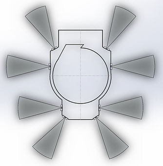
To aid the visualization process of laying everything out, we made a rough model of the base of the mower and added the ultrasonic sensors to see what the coverage would be. To help keep costs low, we are going to print a lot of our parts. To the right is an assembly of our drive system. most of which will be printed.
week 18 (October 1 - 5).


Printed test pieces to test for fit. This will eventually be the drive system.

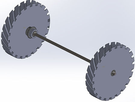
Version 1 and 2 of the axle drive sprocket.
Here are the motors for the back wheels performing an obstacle avoiding loop. When the sensors in the front of the mower are triggered, the mower will reverse, turn, then proceed forward.
week 19 (October 8 - 12).

With the gearbox and motor shafts trimmed, we can assemble and mount them onto the unit. You can also see that the stepper motor drivers have been mounted and a hole was cut for the fan for cooling (not pictured). On the left, the printed pieces were trimmed/assembled and their CAD files were edited for the next round of printing.
week 20 (October 15 - 19).


The final versions of the drive gears and wheels were printed and assembled this week. With almost all of the mechanical modifications complete, we started incorporating the Arduino and sensors onto the unit. We tested the program similarly to what Jennifer did on the bench and it seemed to function correctly. We will now start incorporating the bump sensors and rail.
week 23 (October 28 - Nov 2).

The boundaries for the lawn mowers on the market use wires but with our project, we will not use any guiders as our goal is to have it use the distance sensors to capture the distance and change direction using the compass. The video above shows the idea boundaries for our lawn mower. The mower should go straight from where ever it's at and get close to a limit or boundary and turn right. From there, hit the edge and continue to turn. This program is build into Python called Turtle.
The boundaries for the lawn mowers on the market use wires but with our project, we will not use any guiders as our goal is to have it use the distance sensors to capture the distance and change direction using the compass. The video above shows the idea boundaries for our lawn mower. The mower should go straight from where ever it's at and get close to a limit or boundary and turn right. From there, hit the edge and continue to turn. This program is build into Python called Turtle.
week 23 (November 5 - 9).
week 23 (November 5 - 9).
This week the drive system was finished and tested. In the video above, you can see, the mower moves forward, and when the sensors detect an object is approaching, it stops, changes course avoiding the object, and continues. This is the first step to getting the mower to go around the object and get back on it's original course.
week 23 (November 11 - 16).

The front caster mount was redesigned to provide greater support for the caster wheel along with house the front 3 ultrasonic sensors. A bumper will be designed and added this coming week. Because of the high accuracy of the ultrasonic sensors, the bumpers are being used as a backup in case the ultrasonics miss something, therefore the mower can function without the bumper during initial testing.
The mower was assembled in order to test the movement, as well as the make sure the sensors where working correctly.
week 25 (November 25 - December 1).
During transportation, The holder for the caster broke and the gears seemed to have a dead spot in them causing them not to turn. As you can see there is no direction for the mower as it will not move based on navigation. Please see 'Results' section for update.
week 26 (December 2 - 7).
We notice the speed wasn't to our liking but it is a combination of weight and other factors so we increased the torque from the stepper motors to full load as you can see, it's ready for Nascar now. Results are shown in 'Results' section.